
3D Printing slicing algorithms, their speed and applications
Introduction
Software packages that perform 3d print job preparation usually import parts in the industry standard .stl format (triangles with coordinates in XYZ forming a triangle mesh) and output a file or a set of files that a 3d printer can understand. Most machines require a file that has a "per layer" instruction of what to print. The process of going from a 3d triangle mesh to a collection of 2D layer instructions (slices) is called 'slicing'. The output from a slicer algorithm is usually one of two flavours:
- Pixel based format (for example .png images)
- Vector based format with the coordinates of cross sectional contours. (for example .slc, .svg, .gcode)
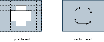
Figure 1: Pixel versus vector based slices
This article will explain two different slicing techniques that are used in slicing software nowadays. What usage applications they are best for and how this all impacts slicing speed and quality. It is based on our experience with Formware 3D and after 3 years of improvements in slicing algorithms.
Technique 1: CPU Slicing
The first method is used by a lot of slicing software in the market and slices your triangle meshes on the CPU (Your computer's processor). That is, all the calculations happen mostly on the CPU. The algorithm to generate 1 slice is roughly as follows:
- For each triangle in your mesh check if it intersects with the horizontal Z plane of the current slice. If so, calculate the line segment following from this intersection. This is part of the cross section that needs to be printed.
- Sort all the line segments for the current slice to form closed polygons. Try to repair any polygons that are not closed or contain other errors.
- Union all overlapping polygons and sort out which ones are holes and which ones aren't.
- Optionally perform any contour offsetting (walls) and hatching (filling) operation if your printer requires this. Usually laser/fdm printers require this step and it is very costly in computational time.
- Export in either of the 2 formats:
- vector based formats (.gcode, .svg, .slc)
- pixel based (.png). For this an additionally 2D image draw and fill operation is required to convert all polygons to filled polygons.
At least steps 1-4 are performed all on your CPU. Optionally step 5 as well. We've summarized the steps in the figure below:
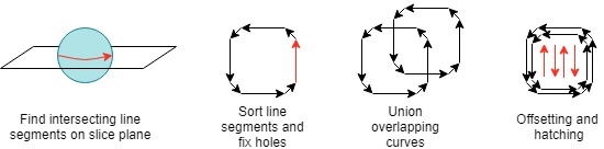
Figure 2: Slicing geometry on the CPU
Technique 1: GPU Slicing
The alternative slicing technique is to let the GPU (your graphics card) do a lot of the heavy lifting. The limitation of slicing on the GPU is that it creates a pixel based output only. A detailed explanation goes to far for this article but the algorithm for generating the slices is roughly the following:
- Make sure all geometry data (triangles) are loaded onto your GPU. This is usually already the case if you are viewing your parts in a 3D View. So this only happens once when loading your part
- Per slice, draw in top view your parts on a specially created pixel buffer (the size of your pixel output.). For each triangle that is drawn, the normal vector tells us if the triangle is downward or upward facing. By keeping count of these two face orientations the GPU can determine if a pixel is inside or outside a model.
- The last part is transferring the generated pixel data from your GPU to your computer memory and saving it as your image based output. (.png slices)
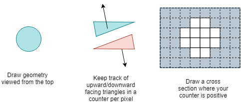
Figure 3: Slicing geometry on the GPU
Challenges in slicing
Now we know what the two main methods are in slicing technology we can look at where the challenges are and how these methods cope with them. The challenges can be roughly categorized as follows:
- Errors in the triangle mesh. This can be amongst others holes, double triangles, inverted triangles etc.
- Very large triangle meshes with 1M triangles and up or a very large amount of parts (translates to 1M triangles and more as well).
- Very large output formats. i.e. pixel based formats of 8000 x 8000 pixels.
- Smooth edges with gray scaling in pixel based slices.
Comparison of methods
We will now compare how both slicing techniques handle these specific challenges and why they might be good or bad.
There can be many different errors in your mesh. For this article it's best to categorize them into 'holes' and 'small artifacts'. Where holes are larger unclosed triangle surfaces in your mesh and small artifacts all other small errors in your mesh (double triangles, degenerate triangles, non-manifold edges, etc.). The CPU slicing method has to loop through each of the triangles and sort out all calculated line segments into closed polygon's. One can imagine that coping with all sorts of small artifacts in your triangles is a very difficult task to do right. However, closing a single hole might be easier to fix by just adding a missing line segment.
When we look at the GPU technique we know that it doesn't care whether there are small artifacts at all. It draws all the triangles mostly simultaneously on the pixel buffer. The only problem in the GPU technique is if there are any horizontal holes in the mesh. Horizontal holes will invalidate the counting of the upward and downward facing triangles. Hence area's might show in your slices where the slicer still thinks it is inside a part where it is actually not.
Next we look at the slicing many triangles. This can either be multiple meshes or one very big mesh. For the GPU that doesn't really matter. By hardware design a GPU is build to do all calculations in parallel. Millions of triangles are processed with ease at an almost constant speed. As a matter of fact it costs often just as much time to transfer the pixel data back to the computer memory (RAM) as it costs to draw all triangles onto the pixel buffer. This is also the reason that when you are slicing a small part (few triangles only) you still experience some processing time with GPU based slicing. The entire pixel buffer has to be transferred from GPU to RAM. This transfer time is independent of whether there are cross sections drawn or not.
A CPU is build to do most of its calculations in serie. One after the other, as fast as possible. When we think of slicing millions of triangles on the CPU it is not hard to imagine that processing all triangles one after the other it might easily be much much slower than in parallel. Even when using multiple cores and multiple threads in your slicing software.
The third challenge a modern day slicer has is to handle large pixel based outputs. Some printers in the marketplace print on resolutions up to 8000 x 8000 pixels. This has consequences for all algorithms creating these slices. Luckily a modern GPU is usually equipped by enough memory to handle these large slices before the pixel data is being transferred over to the computer memory for storage. Creating these large slices with a CPU slicing algorithm will have impacts on your 2D drawing and filling operations of your contours. In our experience not all available drawing libraries are suitable and stable enough to do this.
Last but not least when using a pixel based output for your printer you preferably want to have smooth edges of your cross sections. When slicing on the GPU you can use the highly optimized anti aliasing algorithms developed and perfected for the gaming industry. With a CPU based method the pixel data is potentially generated on the CPU as well. This may limit the anti aliasing result. Mostly however there are fast algorithms available for anti aliasing on the CPU as well. Needless to say, they won’t work in a parallel manner like on the GPU.
Summary
We've talked in this article about two different methods of slicing 3D geometry into 2D layers. There are pro's and con's to each method that we can summarize in a table below.
| CPU | GPU | |
|---|---|---|
| Ability to fix errors | Can handle holes easily. Lots of artifacts are problematic. | Can handle lots of artifacts easily. Horizontal holes are problematic. |
| Handling large amounts of triangles | Processes serial. Very slow with lots of triangles/parts. Very fast with small parts. | Processes parallel. Much faster to process lots of triangles/parts. Has a small startup cost when processing small parts. |
| Creating large slices in pixels | Has consequences for the 2D Drawing/filling algorithms | Most GPU's can easily draw 8000x8000 pixels |
| Smooth edges | Dependent on how well 2D Drawing algorithm smooth edges | Perfect anti aliasing build in already |
Implications for the user
Now we know the differences it is easier to see why slicing on the GPU can have significant advantages in an industrial environment where a pixel based output is required. It is faster when there are lots of parts to be printed. If one knows that the parts contain no errors it is most certainly the best method to slice. Additionally it allows for advanced anti aliasing algorithms and can be easily scaled to high pixel outputs.
How does Formware 3D work
Formware 3D is a software package primarily build for pixel based 3d printers. These are mostly resin and inkjet based machines. As such it has a very robust GPU based slicing algorithm tested on different GPU’s. Over time we developed CPU based slicing algorithms as well and it can currently also slice on the CPU and export .SLC and .GCode formats to work with vector based machines.